

5 Key Lessons When Using Guided Wave Radar
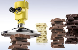
Guided wave radar is a both a popular and an ideal product for measuring level. It’s virtually unaffected by changing process conditions, temperature, pressure, vacuum, vapors and condensation and changes in the measured product properties like conductivity, density and viscosity. Guided Wave works well with solids too, unaffected by dust and uneven surfaces. Temperature ranges are from -196 to 450°C and Pressures up to 400 Bar. Its also simple to understand, a rod or flexible cable extends down over the range you want to measure, you can even cut to length to suit the application (with exception of coated, polished and some special design probes) then install and set it up. That’s simple too: just program min and max levels in relation to the rod or cable and its ready to go. They can also be used to measure level and interface in the right process conditions and operate in stilling tubes, bridles and bypass cages. Our service engineers are setting them up every other day and have given us an insight into some of the most basic issues they regularly see.
The Right Configuration
Buying one off the shelf without paying attention to all the process parameters, or perhaps advice from a supplier, especially if it’s the first application or usage on site. 10 minutes on the phone with a knowledgeable manufacturer before purchasing can save the cost of buying a replacement unit that you should have chosen in the first place, let alone days of frustration and process delays. Also, vessel dimensions and detail of the 0 and 100% positions and relation to volumetric information is invaluable. It is surprising the number of applications where it’s not known at the time of commissioning and/or troubleshooting.
Installation

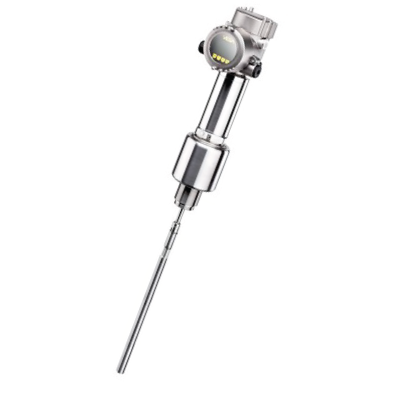
Make sure the GWR is mounted directly into the vessel whenever possible, avoid standoffs as they can cause unwanted interference. If using a concentric probe (see fig 1 – where a rod is inside an outer tube with both attached
to the probe), they are not influenced as the signal path is contained inside. If in a plastic vessel use a metal plate or flange greater than 100mm diameter, this helps to ‘push’ the microwaves in the right direction. It’s said all the time, but it really is worth a look at the manual, ideally, before you buy, it may save you time and further vessel modifications. And, once again a chat and sharing a sketch or drawing with a knowledgeable manufacturer can help you avoid some pitfalls you might not be immediately aware of. Finally, be careful of installing rod probes in agitated vessels, even if it is nowhere near, as long-term fatigue from even a small process movement may cause issues with process seals and signals. Make sure cables can’t touch the sides or internal objects, always install them on an empty silo if measuring solids.
Figure 1 A concentric tube format device helps with poor installations like nozzles but can be susceptible to highly viscous products or long-term internal deposits and build up.
Guide Length
If you cut down the rod or cable length, make sure it’s right! They cannot measure beyond the end, so be careful not to cut too short. Don’t make it too long either, over-length rods that are bolted down and press against the vessel bottom can cause thrust loading damage on seals or touch the vessel side giving a false reading. Cables that are too long have been caught up in outlet valves and screw feeds in silos! Most devices require the user to ‘tell’ the electronics the rod or cable has been cut to a new length, as this enables special safety monitoring and process reaction systems, its normally quite a simple procedure.
Buildup

Careful of buildup in any mounting nozzle, perhaps insulate it if it’s a heated product that sublimates on cooling. Be especially careful if using a concentric tube format between rod and outer tube, or twin rods on high viscosity products, these types of systems often have internal spacers, build up on these can also cause measuring errors and reading hang-ups. Use a single rod format whenever you can. Use minimal spacers (ideally just one at the end) if mounting in a stilling tube or bypass. Explore a contactless measurement format if it’s a high viscosity, a contaminated product that is expected.
Figure 2: Guided Wave Radar installed in bypass with a Magnetic Float Level Indicator as a second technology and side mounted tuning fork switch alarm. These narrow tubes need spacers to ensure the rod is central but be careful about build up on them.
Measuring Oils and Hydrocarbons
All GWR’s have restrictions of measuring at the extremes of range (end of probe and top of probe) especially with hydrocarbons, many users don’t notice this. For example; if measuring oil over a small range of <1 metre in a short oil sump or displacer bridle, it may only operate accurately over the middle third of the range and, at best, lose repeatability at high and low level. Using a concentric tube will help, but that’s not always suitable for reasons given earlier.
Summary
Most of these issues can be evaded by reading technical data and manuals before purchase and during installation. However, time isn’t always on your side, so take a few minutes to discuss your application with a reputable manufacturer, to save potentially hours (and reputations) down the line. Tell them everything you know about the process, the installation and information you are looking to get out… they may even ask questions you don’t have answers for straight away, but a good advisor will explain why it’s needed. Remember they will have learned all the lessons and have everyday experience of many level or interface measurement situations and use that to help you avoid them.